Focus on centrifugal pump manufacturing since 1989
24小时服务热线:sales@zoomlian.com
当前位置: 首页 Horizontal Centrifugal Pump 正文

IR type horizontal single stage single suction centrifugal p_Changsha Zoomlian Pump Co.,Ltd

发布于:2021年04月15日 作者:zlby 阅读:571
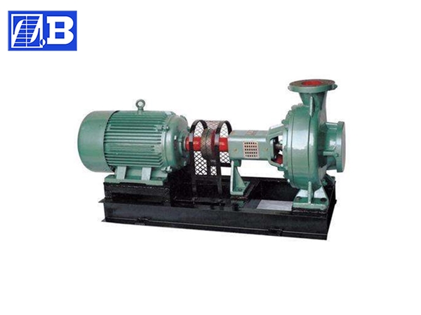
IR type horizontal single stage single suction centrifugal p

IR type horizontal single stage single suction centrifugal p

Capacity: 5.4~400 (m³/h) 

Head: 4~125 (m)

Temperature: 0~150℃ (℃)

IR type horizontal single-stage single-suction clear water centrifugal pump is a nationally designed energy-saving pump. It is an updated type of BA type, BL type and other single-stage clear water centrifugal pumps. The advantages are as follows: the whole series of hydraulic performance layout is reasonable, the user has a wide selection range, and the maintenance is convenient; the efficiency and the suction stroke reach the international average advanced level. This type of pump is suitable for industrial and urban water supply and drainage. It can also be used for agricultural drainage and for the transportation of clean water or other liquids with physical and chemical properties similar to clean water. The temperature is not higher than 150 °C.

IR type horizontal clean water pump ┃ single stage centrifugal pump ┃ clear water centrifugal pump structural features:
 
 
IR type horizontal single-stage single-suction clear water centrifugal pump is designed according to the performance and size specified by national standard ISO2858, mainly by pump body (1), pump cover (2), impeller (3), shaft (4), seal Ring (5), bushing and suspension bearing components (12).
 
The pump body and the cover portion of the IR type centrifugal pump are divided from the back surface of the impeller, that is, the so-called rear door structure. The utility model has the advantages that the maintenance is convenient, and the pump body, the suction pipeline, the discharge pipeline and the electric motor are not moved during the inspection, and only the intermediate coupling of the extension coupling can be removed, and the rotor component can be withdrawn for maintenance.
 
The housing of the pump (ie the pump body and the pump cover) is spliced ​​into the rotor of the pump's working chamber, impeller, shaft and rolling bearings. The suspension bearing component supports the rotor component of the pump, and the rolling bearing is subjected to the radial and axial forces of the pump.
 
In order to balance the axial force of the pump, most of the pump impellers are provided with a sealing ring on the front and rear, and a balance hole is arranged on the rear cover of the impeller. Since some pumps have little axial force, there is no seal ring on the back of the impeller. Balance the holes.
 
The axial seal ring of the pump is composed of a packing gland (9), a packing ring (10), and a packing (11) to prevent intake air or a large amount of water leakage. If the impeller of the pump is balanced, the cavity with the soft packing communicates with the suction port of the impeller. If the liquid at the inlet of the impeller is in a vacuum state, it is easy to enter the air along the surface of the sleeve. Therefore, a packing ring is inserted in the filling chamber. A small hole in the pump cover guides the pressurized water in the pump chamber to the filling ring for sealing. If there is no balance hole in the impeller of the pump, since the liquid pressure on the back of the impeller is greater than atmospheric pressure, there is no problem of steam leakage, so the packing ring may not be installed.
 
In order to avoid shaft damage, the shaft sleeve is protected by the shaft through the filling chamber, and a 0-shaped seal is arranged between the sleeve and the shaft to prevent air intake or leakage along the mating surface.
 
The pump is driven by an extended flexible coupling that is coupled to the motor. The direction of rotation of the pump, viewed from the drive end, rotates clockwise.

IR type horizontal clean water pump ┃ single-stage centrifugal pump ┃ clear water centrifugal pump structure description:
 
 
The IR type horizontal single-stage single-suction clear water centrifugal pump is a rear open type, and it is not necessary to disassemble the water absorption and discharge lines when the pump cover and the impeller are disassembled. Two ball bearings are mounted in the suspension and lubricated with machine oil or grease. The pump is driven directly by the motor via a flexible coupling. The vortex chamber, the foot, the inlet flange and the outlet flange are cast together.
 

IR type horizontal clean water pump ┃ single stage centrifugal pump ┃ clear water centrifugal pump performance range:

 
The IR type horizontal single-stage single-suction clear water centrifugal pump has the advantages of simple structure, reliable performance, small volume, light weight, good anti-cavitation performance, low power consumption and convenient use and maintenance.
 
IR type horizontal single-stage single-suction clear water centrifugal pump has wide versatility. There are 140 kinds of specifications in the whole series, but only four kinds of shafts are used; the shaft, bearing and shaft seal of the same specification can be interchanged; the suspension of the whole series of pumps is also There are only four.
 
The pump speed is divided into 2900 and 1450 rev / min.
 
The performance is as follows: 2900 rev / min 1450 rev / min
 
Maximum flow: 240 m 3 / min 400 m 3 / min
 
Maximum total head: 125 meters 55 meters
 
Maximum speed: 3500 rpm (the impeller diameter is reduced when used for 60-wave power supply)
 
Maximum working temperature: 150 ° C
 
The suction line pressure is allowed to be 0.3 MPa, and the maximum operating pressure of the pump is 1.6 MPa.

IR type horizontal clean water pump ┃ single stage centrifugal pump ┃ clear water centrifugal pump installation:
 
 
First, assembly and disassembly
 
Before the pump is assembled, first check the parts for defects that affect the assembly and scrub them before assembly.
 
1. The connecting bolts and wire plugs of each place can be tightened on the corresponding parts.
 
2. The 0-ring seal, paper pad, felt, etc. can be placed on the corresponding parts beforehand.
 
3. The seal ring and packing, packing ring, packing gland, etc. can be loaded into the pump cover in advance.
 
4. Install the rolling bearing on the shaft, then install it into the suspension, close the gland, press the rolling bearing, and put the connecting bolt on the shaft.
 
5. Set the shaft on the shaft, then install the pump cover on the suspension, and then install and tighten the impeller, the stop pad, the impeller nut, etc. Finally, install the above components into the pump body and tighten the connecting bolts on the pump body and pump cover.
 
In the above assembly process, some small parts such as flat keys, oil pans, and 0-shaped seals in the water-blocking bushings are easy to be drained or clamped, and special attention should be paid.
 
The pump removal sequence can basically be reversed in the assembly sequence.
 
Second, the installation
 
The quality of the pump installation has an important impact on the operation and life of the pump, so installation and calibration must be done carefully. The shape and installation dimensions of the pump.
 
1. Installation and calibration:
 
1) Remove greasy and dirt from the base and place the base on the foundation.
 
2) Check the level of the base with a spirit level, allowing the wedge to be leveled.
 
3) Water the base and anchor bolt holes with cement.
 
4) After the cement is dry, check whether the holes of the base and anchor bolts are loose. After proper fitting, tighten the anchor bolts and check the level.
 
5) Clean the support plane of the base, the pump foot and the plane of the motor foot, and install the water record and motor on the base.
 
6) A certain gap should be maintained between the couplings. Check whether the center line of the pump shaft and the motor shaft are consistent. Use a thin gasket to adjust it to be concentric.
 
Measuring the outer and outer sides of the coupling, the difference between the left and right shall not exceed 0.1 mm, and the difference between the maximum and minimum of the end of the two couplings shall not exceed 0.3 (mm).
 
2, installation instructions:
 
1) The installation height of the centrifugal pump, the length of the pipeline, the diameter and the flow rate should be in accordance with the calculation, and strive to reduce unnecessary losses.
 
2) When transporting long distances, take a larger diameter. The pipeline of the pump should have its own support. The weight of the unsupported pipeline should be added to the pump to avoid crushing the pump.
 
3) If the discharge line is equipped with a check valve, it should be installed outside the gate valve.
 
Third, start stop and run
 
1, start:
 
1) It should be determined whether the rotation direction of the motor is correct before the machine is connected, and whether the operation of the pump is flexible.
 
2) Close the idle valve on the discharge line.
 
3) Fill the pump with water or use a vacuum pump to divert water.
 
4) Turn on the power. When the pump reaches the normal speed, gradually open the gate valve on the discharge line and adjust to the required working condition. If the gate valve on the discharge pipe is closed, the pump should not work continuously for more than 3 times. minute.
 
2, stop:
 
1) Gradually close the gate valve on the discharge line and cut off the power.
 
2) If the ambient temperature is below 0 °C, the water in the pump should be released to avoid cracking.
 
3) If the use is stopped for a long time, the pump should be disassembled, cleaned and oiled, and stored in a package.
 
3. Operation:
 
1). During the driving and running process, you must pay attention to observe the meter reading, the bearing heat, the leakage of the packing and the heat and vibration and noise are normal. If abnormal conditions are found, they should be dealt with immediately.
 
2). The bearing temperature is not more than 80 °C, and the bearing temperature must not exceed 40 °C than the ambient temperature.
 
3). The filler is normal and the water leakage should be a small amount of uniformity.
 
4). The bearing oil level should be kept in the normal position, not too high or too low. When it is too low, the lubricating oil should be replenished in time.
 
5) If the gap between the sealing ring and the impeller is too large, replace it with a new one.
发表评论:

◎欢迎参与讨论,请在这里发表您的看法、交流您的观点。